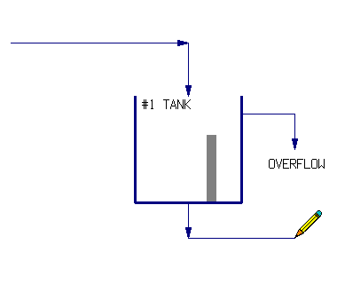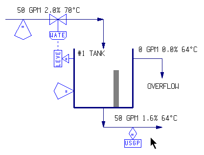
There are three main steps to creating a basic chemical process simulation in CADSIM Plus:
- Create a process sketch or drawing in Drawing Mode.
- Define process chemistry, add formats to display results, answer questions to specify flows, reactions and events in the model using Specification Mode.
- Run and interact with your model and observe the results in Run Mode.
CADSIM Plus is a process engineering tool. It does not, however, do process engineering for you. It is a powerful tool which assists process engineers in doing their work.
Draw a Process Flowsheet
CADSIM Plus contains a full CAD drawing mode that you use to draw your process flowsheet model. You can begin by adding a border to your drawing to set the paper size. You can quickly insert drawing parts by choosing from the hundred’s of prepared parts that are included with CADSIM Plus, or make your own by sketching process shapes to represent units of equipment.

You can clone areas of the drawing and copy them into new locations. Join them by drawing lines which represent pipes. Window an area of the drawing to make a new part to add to your own parts library.
CADSIM Plus Drawing Mode is optimized for flowsheet drawing. Arrowheads are automatically inserted on lines, indicating direction of flow. Smart positioning of text and lines speeds up placement. Line sections are automatically removed where lines cross (but do not join) to make the drawing easier to read. Adder and Splitter units are automatically created where lines join or divide.
Process shapes can be drawn in any form. There are generally no restrictions on the number and positioning of streams entering or leaving general-purpose units such as Tanks. You can use shapes that are familiar to you and to your industry sector.
Make your sketch as simple or as complex as you desire. You can add animations and color changes that are connected to process variables, providing runtime feedback. When you have finished you sketch, move on to defining the process chemistry.
Specify the Process Model
Once your flowsheet is finished, CADSIM Plus enters specification mode where you will be asked to define process chemistry. You can use up to nine different Stream Definitions on up to 256 drawing layers for maximum flexibility in specifying your process simulation model. Choose a stream definition that fits your industry (food, mining, hydrocarbon, pulp and paper, etc.)

Choose from the built-in chemical componds, or define your own compounds using our built-in compound editor. Add your own derived process variables, if desired. Work in US, Imperial or Metric units of measure, or use a mixture of all three.
Once your process stream chemistry is defined, you may add formats to streams and equipment units to display formatted simulation results. Place these formats on lines, inside process shapes, or create tables for them. You can also export results ‘live’ to other programs via DDE, COM or OPC links.
Next, CADSIM Plus will step through your model and prompt you for relationships to satisfy “degrees of freedom” for each variable at each transition point throughout the model (such as where flows divide, or combine, or where they enter or leave a piece of equipment, or where they enter or leave the model). CADSIM Plus insures that your model is not over or under specified. Choose from a variety of equation types to describe your process.
Our stream-based specifications offer maximum flexibility for specifying your process models. In CADSIM Plus, streams are objects that perform their own calculations. You are not limited to specifying your problem within a unit block. In CADSIM Plus it is easy, for example, to specify a flow on one stream, in order to satisfy some relationship found in a different area of the model.
CADSIM Plus creates valve, sensor and other icons for each specification. These icons graphically show the process variables, and make it easy to see how they relate. During runtime, some of these icons are automatically transformed into short-cut PID controllers which you can manipulate to control the simulation (you can use the built-in AutoTune wizard to tune your controllers via the Lambda tuning method at runtime.)
When all of the degrees of freedom are satisfied, CADSIM Plus is ready to run your model.
Run the Simulation
Now you are ready to run your process simulation model. Click on controllers and change flows, or tune controller responses using the Autotune Lambda tuning wizard. Watch as data is logged in strip charts. Tank levels will rise and fall. Pumps may switch on or off in response to changing variables and scripted events, or to a click from your mouse. Logic and Signal diagrams execute your logic events. SmartCalc™ automatically accelerates your model to iterate at thousands of times faster than ‘real time’!

Your sketch has been transformed into a Living Drawing™. Clicking on any line, unit, or control displays dialogue boxes with current simulated results and settings that you can change. These are created for you automatically.
You can export data for further analysis. Insert one or more cases of data into the drawing to be plotted from within CADSIM Plus. Or, create an AutoCAD®; drawing from your CADSIM Plus drawing, or merge results using tags inserted into your existing AutoCAD drawing.
You can return to your drawing and add additional variables. Perhaps you need to add a pressure flow network to one branch of your model? Would you like to study the effects of an additional stage of cleaners? Add alternative configurations by using Dormant and Active layers to add, or remove, additional detail from your model. Perhaps you would like to a Special Component to your model, such as assigning dollar amounts to specific chemicals to create an economic model as part of the simulation. Perhaps you will choose to follow a quality parameter such as Kappa or freeness throughout part of the model.
Your finished model can also be linked via OPC to your plant’s information and control systems. It can used to perform advanced optimization, control or data reconciliation functions.
CADSIM Plus offers you maximum power and flexibility in how your models look and perform. Add the degree of complexity that suits the problem you wish to solve. Scope or de-scope easily to suit a particular problem. It’s all possible with CADSIM Plus.
Is CADSIM Plus right for you?
Find out how to get started with CADSIM Plus!
Click to e-mail or call us at 604.299.7707
